|
|
|
|


|
|
|
| |
|
TRANAIR++ was originally developed soley as a three dimensional solver. A two dimensional equivalent
version of TRANAIR was developed in 1989 and it now has the same capabilities and features as the
original three dimensional version. |
|
|
|
TRANAIR++ solves a nonlinear, full potentiall equation to analyze the aerodynamic properties of a given geometry. TRANAIR++ provides accurate results in compressible (supersonic, transonic, and subsonic), attached or mildly seperated flows.
|
|
|
| |
|
|
|
|
|
|
|
Viscous effects in transonic flow may be approximately modeled for within the TRANAIR++ code through invocation of boundary layer coupling. The boundary layer coupling implemented in TRANAIR is a pseudo-3D approach based on either an infinite swept wing with taper approximation or an axisymmetric approximation. These approximations may be used to apply boundary layer coupling to "wing-like" surfaces, nacelles and bodies.
The solution of the boundary layer equations is driven by the pressure field (or velocity distribution) on the configuration surfaces. The boundary layer solution provides a set of transpiration boundary conditions for the inviscid solver.
A viscous solution is computed in TRANAIR++ by coupling with the ISES boundary layer code developed by Mark Drela at MIT. The TRANAIR++ viscous coupling can be described as "closely coupled" in the sense that the equatoins for the inviscid flow and the coupling equations are combined and solved together using Newton's Method. This boundary layer coupling can solve for mildly separated flows in addition to attached flows.
|
|
|
|
|
Once the computational domain is established, a uniform global grid is constructed in that region. This global grid of rectagnular boxes (cells or elements) is further refined hierarchically (i.e., each box that is refined gives rise to eight smaller boxes), producing the final computation grid. Construction of such a grid is automated within the code and no surface conforming grid generation is required. Near the surfaces the grid elements are cut by the boundary into general polyhedral shapes.
TRANAIR++ then generates a sequence of grids which are used to solve the problem. The coarsest grid in the sequence comes first. The discretization is generated on this grid and the equations are solved. This solution is interpolated to the next (finer) grid whoes refined cells are focused on areas of high velocity gradient according to the previous solution. This process is repeated until the solution is obtained on the finest grid in the sequence as specified by the user. |
|
|
|
|
In general the flow will be divided into seperate flow regions by the input geometry. These regions can have different flow properties. In the simple wing/body case there is a freestream region (outside the aircraft) and a stagnation region (inside the aircraft). If a nacelle is present it is possible to model the engine on effects by defining the exhaust plume region and prescribing the appropriate material properties in these region. The geometry defines the flow regions and the user prescribes the flow properties. So, for example, a simple nacelle will have three types of flow regions (freestream, stagnation, and exhaust plume) contained by four types of surfaces (body or stagnation, fan face, exhaust face, and a wake surface seperating plume from freestream).
|
|
|
|
The TRANAIR++ design option allows the user to modify their existing geometry to obtain a new configuration with enhanced properties. The design method is a direct design method that allows the user to define the geometry movemen, geometry and flow constraints, and objective functions. This type of approach allows very general problem formulations, but requires the optimization problem to be well-posed in order to obtain a reasonable solution. Through the use of the post processing tool dgraf the geometry movement routines can be verfied by a visual check of the movement routines. This check can be performed before the optimizer run, saving valuable time in the debugging process while writing the movement routines.
|
|
|
|
|
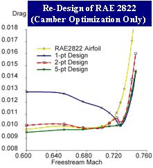 |
A brief description of TRANAIR++'s abillity to design is provided in the design feature section. The user can accomplish a drag minimization design by setting the objective function to the sum of induced drag, profile drag, and wave drag. A major flaw in this approach is the well-known problem of obtaining a "point" design solution, namely, a geometry which has very low drag at the flow conditions where the design was performed, and worse than nominal drag at some other flow conditions which occur during the normal flight plan. Multi-point design can help prevent these "off" design problems.
|
|
|
|
tgraf is a utility used to interrogate and display selected data from a TRANAIR solution set. dgraf is the design equivilant of tgraf, allowing the manipulation of geometry through the user defined movement functions. The following are some of the post processing capabilities of tgraf and dgraf.
- View input geometry and volume grids created by TRANAIR++
- Rotate, scale, and translate the solution
- Volume and planar cuts
- Isosurfaces (surfaces of constant scalar property)
- Streamlines
- Painting of geometry and slices with a scalar property
- Hidden surface and line removal
- Scripting
- Perturbation movement (dgraf)
|
 |
|
|
|
